Dấu kích thước của bản vẽ thiết kế khuôn
Dấu kích thước của bản vẽ thiết kế khuôn
I. Yêu cầu chung về đánh dấu kích thước trong bản vẽ thiết kế khuôn
1. Các đơn vị được sử dụng để đánh dấu kích thước: Các đơn vị kích thước trong bản vẽ khuôn bao gồm các hệ thống số liệu và đế quốc. Trong số đó, các quốc gia như Vương quốc Anh, Hoa Kỳ, Canada, Ấn Độ và Úc sử dụng hệ thống đế quốc, trong khi Trung Quốc sử dụng hệ thống số liệu. Tuy nhiên, nếu khách hàng đến từ bất kỳ quốc gia nào ở trên, nên sử dụng hệ thống đế quốc. Ngoài ra, nhiều bộ phận tiêu chuẩn trong khuôn (như ốc vít, thanh đẩy, v.v.) nằm trong các đơn vị đế quốc. Do đó, ngay cả khi các kích thước khác trong các hệ thống số liệu trong quá trình thiết kế khuôn, kích thước của các bộ phận tiêu chuẩn này vẫn được đánh dấu trong các đơn vị đế quốc.
2. Độ chính xác được thông qua khi đánh dấu kích thước.
Kích thước tuyến tính: Hệ thống số liệu sử dụng hai vị trí thập phân X.XXMM và Hệ thống Imperial sử dụng bốn vị trí thập phân X.xxxxin.
Góc: Sử dụng một vị trí thập phân: X.X °.
3. Tham chiếu chiều trong bản vẽ khuôn
Một. Sản phẩm (Phần nhựa) Tham khảo: Tài liệu tham khảo dựa trên bản vẽ sản phẩm của khách hàng. Tất cả các kích thước của khoang và lõi phải dựa trên tham chiếu phần nhựa làm tham chiếu thiết kế.
Kích thước của lõi và khoang trong bản vẽ thiết kế khuôn sẽ tương ứng một-một với các hình trong bản vẽ sản phẩm.
b. Tham chiếu lắp ráp khuôn: Nói chung, trung tâm của cơ sở khuôn được lấy làm tham chiếu lắp ráp. Tất cả các kích thước liên quan đến việc lắp ráp cơ sở khuôn, chẳng hạn như lỗ vít và các lỗ nước làm mát, nên được dựa trên tham chiếu lắp ráp như tham chiếu thiết kế.
c. Tài liệu tham khảo quy trình: Tham chiếu được xác định dựa trên các yêu cầu xử lý và đo lường của các bộ phận khuôn, chẳng hạn như đối trọng của lỗ chèn phải dựa trên bề mặt dưới cùng
Phương pháp lựa chọn của tham chiếu chiều cho bản vẽ khuôn như sau
Một. Trong chế độ xem mặt cắt, bề mặt chia tay được lấy làm tham chiếu và các ký hiệu tham chiếu được thêm đồng thời. Đôi khi, các kỹ sư sản phẩm có thể yêu cầu một tham chiếu dựa trên bản vẽ phần nhựa. Trong những trường hợp như vậy, tham chiếu phần nhựa trùng với đó trong bản vẽ khuôn
b. Trong kế hoạch sàn, tình hình khá phức tạp và nên được đối xử khác nhau.
Nếu phần nhựa đối xứng, hãy sử dụng hai dòng trung tâm làm tài liệu tham khảo và thêm các ký hiệu tham chiếu cùng một lúc.
Nếu chỉ có một trục đối xứng trong khi cái kia không đối xứng và nếu có vị trí cột, thì trung tâm của cột nên được lấy làm tham chiếu. Nếu không có vị trí cột, hãy lấy đường thẳng dài hơn hoặc cạnh thẳng làm tham chiếu.
Nếu cả hai trục đều không đối xứng, hãy chọn vị trí cột hoặc phía thẳng làm tham chiếu.
Việc lựa chọn chính xác các tài liệu tham khảo kích thước là một điều kiện quan trọng để đảm bảo các yêu cầu thiết kế của các bộ phận và tạo điều kiện xử lý và đo lường.

Nhà sản xuất khuôn quạt ở Trung Quốc (jfmoulds.com)
4. Kích thước của cùng một cấu trúc phải đồng đều trong các nỗ lực khác nhau. Ví dụ, đánh dấu đồng đều theo kích thước cuối lớn. Nếu cần thiết, góc giảm cũng nên được đánh dấu, chẳng hạn như 50 ± 3 °. Đối với kích thước của các sườn gia cố (RIB) và lỗ, chỉ cần kích thước trung tâm, chiều rộng, độ sâu và đường kính cần được đánh dấu. Góc độ giảm nên được đánh dấu riêng.
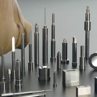
5. Vị trí và kích thước của các lỗ thanh đẩy chỉ cần được đánh dấu trên bản vẽ chèn khuôn bên trong. Chúng không cần phải được đánh dấu trên tấm cố định thanh đẩy hoặc bản vẽ mẫu, nhưng phải chỉ định đường kính của các lỗ thanh đẩy.
6. Đối với các bộ phận gia công của CNC, không cần thiết phải đánh dấu tất cả các kích thước. Chỉ các dữ liệu tham chiếu quan trọng và dữ liệu kiểm tra mới cần được đánh dấu.
7. Các kích thước chính được đánh dấu trên các phần chèn di chuyển và cố định là: cắt dây; Ốc vít, lỗ nước làm mát, đẩy lỗ thanh; Chênh lệch chiều cao của bề mặt chia tay; Các kích thước phù hợp của hình dạng, vv Để rõ ràng, ở trên có thể được đánh dấu trên một hoặc nhiều bản vẽ.
8. Đối với kích thước cắt dây, chỉ nên đánh dấu kích thước chính. Đối với các đường viền phức tạp, phần cắt dây có thể được sao chép và vẽ riêng, và ghi chú trên bản vẽ gốc.
9. Các cơ sở trang trọng không chuẩn cần được đánh dấu bằng các vị trí và kích thước của các lỗ vít loại mẫu, thanh đặt lại, ghim hướng dẫn, v.v. Tuy nhiên, các cơ sở định dạng tiêu chuẩn không cần phải được đánh dấu (và các chân hướng dẫn, đặt lại thanh và chân hướng dẫn tấm thanh đẩy không còn được đặt hàng trong các phần tiêu chuẩn).
Khi đánh dấu vị trí xử lý của điện cực sườn cốt thép, chỉ cần đánh dấu vị trí trung tâm của điện cực.
Khuôn đúc Ô Tô Công ty TNHH khuôn đúc jiefeng thái Châu (jfmoulds.com)
Ii. Requirements for Dimension Marking of Assembly Drawings
1. The ranking map adopts the coordinate annotation method, with the center of the mold as the coordinate origin. The sectional view adopts linear dimensioning.
2. The assembly drawing mainly marks the following dimensions.
a. Dimensions of the connection parts of the injection molding machine;
b. The dimensions of all parts that are not separately drawn in the part drawing (mainly the processing part of the mold frame), but the positions of the standard holes on the mold frame may not be marked
c. Position and size of each cavity, and try to take the nearest whole number;
d. The position of the gate and the gate sleeve screws;
e. The size of the template and the size and position of the inner mold inserts;
f. The position and size of the lateral core-pulling mechanism and its accessories;
8. The position and size of the positioning block;
h. Location, specification and number of cooling water holes;
The diameter and position of holes i.K.O;
J. The length and size of the guide pins and guide sleeves of the push rod plate;
k. Position and diameter of the support columns (S.P);
1. The diameter and length of the reset spring, the depth and diameter of the spring hole, and the spring specification should be marked;
m. The diameter and thickness of the limit nail;
n. The position and length of the spacing parting mechanism in the three-plate mold and the two-plate half-mold.
Three: Requirements for dimension marking of parts
1. Correct: Dimensional marking should comply with the basic provisions of the national standard "Mechanical Drawing"
2. Completeness: Dimensional annotations must ensure that all production activities in the factory can proceed smoothly and facilitate reference and search based on the drawings.
3. Clarity: The size configuration should be uniform and standardized
4. Reasonable: The dimensional marking should comply with the design and process requirements to ensure the performance of the mold.
5. For parts with a slope, the "large" and "small" should be noted beside the dimension marking to indicate the dimensions of the large and small ends.
6. Basic Requirements: The maximum external dimensions must be directly marked on the drawing. If a closed dimension chain is generated, parentheses can be added to the maximum external dimension.
7. Dimensions should be marked outside the view as much as possible to avoid the intersection of dimension lines, dimension numbers and the contour lines of the view.
8. The diameter dimensions of concentric cylinders are best marked on non-circular views
9. Parallel dimensions should be arranged in order of size, with smaller dimensions inside and larger dimensions outside, and their dimensions should be adjusted accordingly
10. The dimension lines should be neatly arranged, and they should be placed on the same side as much as possible. It is best to arrange the relevant dimensions in a straight line. The size numbers are staggered. In densely populated areas, the markings should be enlarged to avoid misunderstandings.
11. Important positioning dimensions in the cavity, such as holes, ribs, and grooves, should be directly marked on the reference.
12. All structures must have positioning and shaping dimensions. For the positioning dimensions of holes, ribs and grooves, the center line should be taken as the standard.
13. When marking the dimensions of sectional views, to ensure clarity, clarity and neatness, the inner and outer dimensions should be marked on both sides respectively.
Four: Examples of Dimension Marking on Mold Design Drawings
(1) Examples of dimension marking on mold assembly drawings: Due to the large number of dimensions to be marked on the assembly drawing, for the sake of clarity, in the actual working process, the main section views in the assembly drawing are not marked with section lines.
(2) An example of dimension marking for the B board of the moving mold
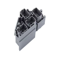
The structure of the moving die B plate includes: die frame, cooling water circuit, screw holes, push rod (push tube) holes, reset rod holes, holes of the spacing and parting mechanism, and sometimes a lateral core-pulling mechanism, etc. An example of dimension marking is shown in Figure 1-27. The X and Y directions are marked by the coordinate method, with the center line of the mold as the reference. The height dimensions are marked using the linear marking method, with the bottom surface of the template as the reference. Different push rod through holes are represented by different symbols, and their sizes and quantities are listed together
(3) Examples of dimension marking for fixed mold A plates
The marking method for Board A is the same as that for board B
(4) Examples of internal mold insert dimension marking: Generally, insert diagrams are divided into insert screw hole diagrams, cooling water channel diagrams, and insert processing diagrams. The
shape of the insert is simple. The screw holes, cooling water circuit diagram and processing drawing are reflected on the same drawing. Precautions when marking the insert:
1. The direction and reference Angle should be accurately marked on the die side.
2. Express the drawing completely with the fewest views, and mark the dimensions of a shape as clearly as possible on one view.
3. The surfaces that are bumped through and rubbed through should be marked with words.
4. The parting surfaces should be marked according to the positions on the assembly drawing. The reference angles should be specified and the references should be consistent with those on the assembly drawing.
5. For quenched inserts, the draft Angle of the inner mold insert forming surface should be indicated. If the draft Angle of the cavity is 1.5°, the marked size should be the large head (end) size.
Thông tin liên quan
Các phần tiêu chuẩn của khuôn
2025-07-24
Các bộ phận tiêu chuẩn của khuôn mẫu khuôn mẫu khuôn tiêu chuẩn của khuôn mẫu O ...
Nguyên nhân và giải pháp của bong bóng, dính nấm mốc và dính vào các sản phẩm đúc phun
2025-07-31
Các nguyên nhân và giải pháp của bong bóng, dính khuôn và cổng dính vào tiêm ...

Những khiếm khuyết phổ biến của các sản phẩm đúc phun và các giải pháp của chúng
2025-07-29
Những khiếm khuyết phổ biến của các sản phẩm đúc phun và các giải pháp của họ trong chẩn đoán ...
Thiết bị quan trọng trong lĩnh vực hậu cần và kho bãi
2025-06-29
Thiết bị quan trọng trong lĩnh vực hậu cần và nhà kho khuôn nhà sản xuất tại...
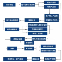
Một bộ sưu tập các quy trình sản xuất khuôn mẫu, tiêu chuẩn, quy trình và vỏ.
2025-06-19
Biểu đồ Lưu lượng quá trình như sau: tất cả các loại công cụ và sản phẩm được sử dụng trong...

Nowon thay mặt cho "ảo thuật gia đúc khuôn" chính xác trong ngành sản xuất
2025-06-29
Nowon thay mặt cho "Nhà ảo thuật đúc khuôn" chính xác trong ngành sản xuất hiện nay...