Sự sắp xếp khoang và bề mặt phân chia của khuôn
Sự sắp xếp khoang và bề mặt phân chia của khuôn
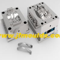
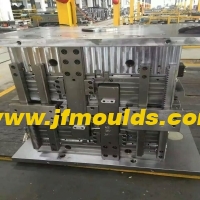
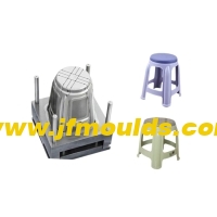
Các bộ phận tạo hình đề cập đến các bộ phận khuôn tham gia trực tiếp vào việc hình thành không gian khoang, chẳng hạn như khuôn quay lại (khoang), chày (lõi), mảnh, kéo lõi bên, v.v. Khi thiết kế các bộ phận đúc, cần xem xét đầy đủ đến tốc độ co rút của khuôn nhựa, độ dốc khi đúc và khả năng xử lý để sản xuất và bảo trì.
Việc thiết kế các bộ phận định hình nói chung có thể được thực hiện theo các bước sau
① Xác định số lượng khoang khuôn
② Xác định vị trí của khoang.
③ Xác định đường phân khuôn của phần nhựa và bề mặt phân khuôn
④ Khi cần kéo lõi ngang, hãy thiết kế cơ cấu kéo lõi ngang.
⑤ Xác định kích thước tạo hình của khoang lõi và Góc nghiêng
⑥ Xác định phương pháp kết hợp và cố định của các bộ phận tạo hình
Nhà sản xuất khuôn phân ở Trung Quốc (jfmoulds.com)
Xác định số lượng lỗ sâu răng
Nếu máy ép phun phù hợp với khuôn đã được xác định trước thì số lượng khoang có thể được xác định theo hai cách sau
(1) Theo lượng phun định mức của máy phun được sử dụng
(Tổng trọng lượng các bộ phận nhựa trong mỗi khoang + bê tông trong hệ thống cổng) 80% thể tích phun định mức của máy phun
(2) Theo lực kẹp định mức của máy phun
Giả sử tổng diện tích hình chiếu của mỗi khoang và phần chạy trên bề mặt phân khuôn là phần S (mm 2), lực kẹp định mức của máy phun là phần F và áp suất trung bình của nhựa nóng chảy lên khoang là loại, thì
S Khóa hộ gia đình loại F x 80%
Một: Căn chỉnh khoang
Nguyên tắc xếp hạng
① Nguyên tắc của kênh dòng chảy ngắn nhất: Giảm vật liệu đông đặc trong hệ thống cổng và tiết kiệm chi phí sản xuất thép và khuôn mẫu.
② Nguyên tắc cân bằng nhiệt độ: Đảm bảo nhiệt độ ở tất cả các bộ phận của khoang khuôn xấp xỉ bằng nhau để đảm bảo tốc độ co ngót của các bộ phận nhựa trong mỗi khoang là như nhau.
③ Nguyên lý cân bằng áp suất: Đảm bảo hợp lực của lực kéo mà khuôn chịu trong quá trình ép phun gần tâm khuôn và thẳng hàng với lực kẹp của máy ép phun.
④ Nguyên tắc cân bằng cấp liệu: Đối với các khuôn có nhiều khoang trong một khuôn, cùng một bộ phận nhựa phải được cấp liệu từ cùng một vị trí để đảm bảo khả năng thay thế lẫn nhau của các bộ phận nhựa. Kích thước và chiều dài của đường dẫn và cổng phải phù hợp với kích thước của bộ phận nhựa và cần đảm bảo rằng tất cả các khoang được nạp và lấp đầy đồng thời càng nhiều càng tốt.
Những lưu ý khi bố trí các khuôn có nhiều khoang trong một khuôn.
Các bộ phận bằng nhựa lớn hơn hoặc phức tạp hơn nên được đặt gần đường dẫn chính, tức là ống bọc cổng. Tuy nhiên, khoang không được bố trí càng nhiều càng tốt trong phạm vi đường kính 30 mm xung quanh ống bọc cổng hoặc độ dày thép từ khoang đến ống bọc cổng ít nhất phải là 8 mm.
Đối với các khuôn có nhiều khoang trong một khuôn, độ dày thép A giữa mỗi khoang và độ dày thép B từ khoang đến mép của lớp lót khuôn bên trong có thể được chọn dựa trên độ sâu của khoang. Khoang càng sâu thì độ dày thép càng dày.
Special circumstances include:
When a concealed gate is used, there should be sufficient space for the concealed gate and the position for arranging the push rods
b. When the plastic part is large in size and the cavity is deep (60mm)
c. The size of the plastic part is relatively large, and the inner model core is inlaid through. At this point, the insert forms a frame structure 1 with poor rigidity. The steel thickness should be increased to enhance rigidity.
When cooling water needs to be passed between the cavities, the distance between the cavities should be larger to ensure that the steel thickness between the cavities and the cooling water channels is no less than twice the diameter of the water channels.
Sure enough, when the mold needs to be core-pulled from the side, the sequence should give priority to core-pulling from the left and right sides, and try to avoid core-pulling up and down.

Two: Parting surface
The main contents of parting surface design
The main contents of parting surface design are as follows.
① Position of the parting surface: Which part is formed by the moving mold and which part is formed by the fixed mold.
② Shape of the parting surface: Is it a plane, an inclined surface, a stepped surface or an arc surface
③ Positioning of the parting surface: How to ensure the positional accuracy of the core and cavity, and ultimately guarantee the dimensional accuracy of the plastic part
2. General principles for the design of parting surface positions
(1) The principle of aesthetic appearance
The selection of the parting surface should minimize its impact on the appearance of the plastic part. Especially for plastic parts with clear requirements for appearance, more attention should be paid to the influence of the parting surface on the appearance
(2) The principle of convenient processing
The selection of the parting surface should make the mold structure simple and easy to process, especially for the processing of the core and cavity.
(3) The principle of easy molding
The selection of the parting surface should be conducive to the pouring of the melt, the venting of the cavity and the design of the cooling system. Usually, when designing the parting surface, designers often encounter problems where there are more than two demolding directions on the plastic part.
For the shorter stroke demolding direction, the slider is used for lateral core-pulling. However, when the lateral core-pulling mechanism closes the mold, the clamping force it can provide is relatively small. If the projected area of the plastic part in this direction is large, problems will occur. For molds with inserts, the simplicity and convenience of insert installation should also be taken into consideration.
(4) Smooth demolding principle
The selection of the parting surface is conducive to the demolding of the plastic part, ensuring that the plastic part remains on the side with the ejection mechanism during mold opening (sometimes it is.
(Moving mold, sometimes fixed mold.)

Three: Shape design of the parting surface
The shape of the parting surface is best when it is a plane perpendicular to the mold opening direction, followed by inclined surfaces, then smooth arcs, stepped surfaces, etc. The parting surface shall not have sharp corners or edges. Sharp corners and edges will make processing more difficult and also affect the sealing material of the parting surface and the service life of the mold.
(1) Step parting surface
There are multiple options for the parting surface of this plastic part, and the final choice often depends on the customer's requirements.
(2) Inclined parting surface
The inclined parting surface should be equipped with a stop mouth positioning surface to counteract the horizontal component of the expansion force. The positioning surface is determined based on the actual situation and can be on either side. Both (a) and (b) are acceptable. The inclination Angle of the positioning surface. It is generally 10 "to 15". The greater the slope, the worse the positioning effect. The inclined parting surface should extend outward by 5 to 10mm according to the Angle of the parting surface to prevent the edge of the cavity from cracking and to avoid movement during the FIT mold.
(3) Curved surface parting surface
The design of the curved surface parting surface is roughly the same as that of the inclined surface parting surface. In the figure, A=5 to 10mm, and the inclination Angle ea is generally 10 to 15°
(4) The parting surface that is rubbed through or bumped through on the side
If the threading as shown in Figure 4-5(b) is adopted, the formed plastic part has no wire clamping, as shown in Figure 4-5(d), but the plastic part is prone to flash, and the flash is balanced with the side hole, reducing the size of the hole. When rubbing through, it is best to have a slope of 3 or more on the side. If the piercing method is adopted, the plastic part can see the wire clamping, but it is not easy to have flash. Even if there is flash and it is perpendicular to the hole, it does not affect the size of the hole. a is taken as 6°-10°. If c is chosen, it can be suggested that the customer make a slope of 3° to 5° on each side of the bump hole, so that there will be no wire clamping.
(5) The parting surface of the inclined square hole
The inclined square hole should be given priority for penetration. The condition for penetration is that if a<1° in the figure, the lateral core-pulling a 3° should be given priority.
(6) There is a raised parting surface on the side
There is a raised structure on the side. The parting surface should be prioritized for lifting, but this will cause wire clamping. Moreover, since the draft angles of the moving and fixed molds are exactly opposite, the wire clamping on both sides will have obvious lifting, affecting the appearance. If the customer cannot accept it, only lateral core-pulling can be adopted.
(7) Piercing and rubbing through on the parting surface
"Piercing through" refers to the contact surface of the moving and fixed mold forming parts being perpendicular to or roughly perpendicular to the mold opening direction; otherwise, it is called "rubbing through". When the contact surface is parallel to or approximately parallel to the mold opening direction, it is also called penetration. From the perspective of the convenience of mold manufacturing, the sealing surface on the parting surface should be pierced by impact as much as possible to avoid being rubbed through. Except for round holes which can be pierced by insertion, insertion is generally prohibited for non-round holes. When there are large through holes on the plastic part and the impact penetration surface on the mold is large, the middle of the impact penetration surface should be left empty to reduce the impact penetration area and facilitate the FIT mold.
Khuôn đúc hàng hóa Công ty TNHH khuôn đúc jiefeng (jfmoulds.com)
Four: Positioning of the parting surface
The guide pins and guide sleeves of the moving and fixed molds are clearance fits. They mainly serve to guide. The positional accuracy of the formed parts must be guaranteed during the design of the parting surface. If the plastic part is complex and the parting surface is inclined or curved, the shape and size of the sealing surface, how to position it, and there must be a measurement reference when designing the parting surface must be taken into consideration.
Even for planar parting surfaces or stepped parting surfaces, in order to improve accuracy, conical surface positioning is sometimes designed on the parting surface.

Thông tin liên quan

Dấu kích thước của bản vẽ thiết kế khuôn
2025-09-10
Dấu kích thước của bản vẽ thiết kế khuôn. Yêu cầu chung cho Dimensio ...
Các giải pháp cho vấn đề dễ bị vỡ ở ngã ba của sự khác biệt màu sắc ngoại hình của khuôn và dòng chảy vật liệu
2025-09-05
Giải pháp cho vấn đề dễ bị vỡ tại ngã ba của khuôn xuất hiện ...
Nguyên nhân của khiếm khuyết trong các sản phẩm đúc phun
2025-07-27
Nguyên nhân của khiếm khuyết trong các sản phẩm đúc phun phần điện của ...

Các rãnh của đầu vào không khí phun của khuôn, ánh sáng và bóng bề mặt, các vết trầy xước trên các rãnh và kích thước của các lỗ vít đã tăng lên
2025-08-13
Các rãnh của đầu vào không khí phun của khuôn, ánh sáng và bóng bề mặt, ...
Các nguyên nhân và giải pháp của các vệt bạc, sự đổi màu, gợn sóng bề mặt và độ nhám trong các sản phẩm đúc phun
2025-07-30
Các nguyên nhân và giải pháp của các vệt bạc, sự đổi màu, gợn sóng bề mặt và r ...
Sự sắp xếp khoang và bề mặt phân chia của khuôn
2025-10-09
Sự sắp xếp khoang và bề mặt phân chia của khuôn Các bộ phận tạo hình tham khảo ...