Giới hạn ghim và lò xo của khuôn
Giới hạn ghim và lò xo của khuôn
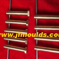
Một: Chân giới hạn
Chức năng của đinh giới hạn là tạo ra một khoảng cách nhất định giữa tấm thanh đẩy và tấm dưới cùng của khuôn di chuyển, ngăn chặn sự biến dạng của mẫu hoặc kết nối giữa tấm thanh và khuôn chuyển động
Rác rơi giữa các tấm đáy khuôn, khiến các tấm que đẩy không đặt lại chính xác. Giới hạn móng tay, thường được gọi là đinh rác, thường được làm bằng vật liệu P-20.
(1) Đặc điểm kỹ thuật và mô hình của pin giới hạn
Có hai hình dạng tiêu chuẩn của các chân giới hạn.
Nhà sản xuất khuôn đèn ô tô ở Trung Quốc (JFMOULDS.com)

(2) Kích thước của pin giới hạn
(3) Lắp ráp móng tay giới hạn
Các chân giới hạn nên được lắp đặt trên tấm đế của khuôn di chuyển. Đối với các chân giới hạn tích phân, nên áp dụng sự phù hợp với sự can thiệp.
Vị trí của pin giới hạn. Nên thêm móng tay trong tất cả các thanh đặt lại, tại các khu vực dày đặc của thanh đẩy và dưới các thanh đẩy nghiêng để chịu được lực giãn nở trong quá trình phun nấm mốc.
Hai: Mùa xuân

Trong khuôn, các lò xo chủ yếu được sử dụng làm công suất phụ trợ cho các thành phần di chuyển như thiết lập lại của tấm thanh đẩy, định vị của thanh trượt trong cơ chế kéo lõi bên, và khoảng cách và chia tay của mẫu di chuyển. Vì lò xo thiếu lực đẩy cứng và dễ bị thất bại mệt mỏi, nên chúng không được phép sử dụng một mình
Sử dụng. Các lò xo trong khuôn bao gồm lò xo màu xanh hình chữ nhật và lò xo đen tròn. Bởi vì các lò xo màu xanh hình chữ nhật có hệ số đàn hồi lớn hơn, độ cứng mạnh hơn và tỷ lệ nén lớn hơn so với lò xo đen tròn, lò xo màu xanh hình chữ nhật thường được sử dụng trong khuôn.
(1) Lò xo đặt lại tấm thanh đẩy
Đẩy tấm thanh đẩy trở lại vị trí ban đầu của nó. Lò xo đặt lại thường được sử dụng là một lò xo màu xanh hình chữ nhật, nhưng nếu khuôn lớn và có nhiều thanh đẩy, nó phải là
Xem xét sử dụng lò xo hình chữ nhật màu xanh lá cây hoặc cà phê. Khi chọn một hình thu nhỏ tải ánh sáng, các khía cạnh sau đây cần được lưu ý.
1. Lượng tải trước và tỷ lệ tải trước
Khi tấm thanh đẩy trở về vị trí ban đầu của nó, lò xo vẫn cần duy trì một lực đàn hồi trên tấm thanh đẩy. Lực này xuất phát từ áp suất cao nhất của mùa xuân, và áp suất thường được yêu cầu là khoảng 10% chiều dài miễn phí của mùa xuân.
Lượng tải trước chia cho chiều dài miễn phí cho tỷ lệ tải trước. Đối với lò xo có đường kính lớn hơn, nên chọn tỷ lệ tải trước nhỏ hơn.
Khi chọn lò xo trở lại cho tấm thanh đẩy khuôn, tỷ lệ tải trước thường không được sử dụng, nhưng lượng tải trước được áp dụng trực tiếp. Điều này có thể đảm bảo rằng, trong điều kiện có kích thước đường kính lò xo nhất quán, tải trước áp dụng cho tấm thanh đẩy không bị ảnh hưởng bởi chiều dài tự do của lò xo. Tải trước thường được lấy là 10,0 đến 15,0mm.
2. Lượng nén và tỷ lệ nén
Lò xo nén thường được sử dụng trong khuôn. Khi tấm thanh đẩy đẩy phần nhựa ra, lò xo được nén và lượng nén bằng với khoảng cách phần nhựa được đẩy ra. Tỷ lệ nén là tỷ lệ của lượng nén so với chiều dài tự do. Nói chung, theo yêu cầu tuổi thọ dịch vụ, tỷ lệ nén của lò xo xanh hình chữ nhật là từ 30% đến 40%. Tỷ lệ nén càng nhỏ, tuổi thọ dịch vụ càng dài.
3. Số và đường kính của lò xo đặt lại
4. Xác định chiều dài miễn phí của mùa xuân
① Free length calculation: The free length of the spring should be determined based on the compression ratio and the required compression amount. In the formula L free =(E P)/S
E is the stroke of the push rod plate, E= the minimum distance the plastic part is pushed out 15 to 20mm.
P represents the preload amount, which is generally taken as 10 to 15mm. It is determined based on the resistance during reset. The smaller the resistance, the smaller the preload. Usually, it can also be selected according to the size of the mold frame. For mold frames 3030(inclusive) or less, the preload amount is 5mm; for mold frames 3030 or more, the compression amount is 10 to 15mm.
S represents the compression ratio, typically taken as 30% to 40%. The free length should be determined based on factors such as mold life, mold size, and the distance between plastic parts. The standard length should be taken upwards.
If the calculated length is greater than the minimum length Lmin, the calculated length shall prevail.
The free length must be in accordance with the standard length and must not be cut for use. It is preferred to use multiples of 10
5. Assembly of the reset spring

(2) Design of the slider positioning spring in the lateral core-pulling
The spring in the lateral core-pulling mechanism mainly serves a positioning function. After the mold is opened, when the inclined guide column and the wedge block leave the slider, the spring holds against the slider and does not slide back. The commonly used diameters of springs are 10mm, 20mm and 25mm. The pressure ratio can be 12mm or 16mm, and the compression ratio can be 1/4 to 1/3. The quantity is usually two.
Calculation of the free length of the slider spring: L free two-slider stroke S×3, where S is the core-pulling distance of the slider. Freedom is the free length of the spring, and the standard length should be taken upwards.
B = Free length - preload - core-pulling distance
The preload amount can be determined through calculation: slider preload amount - pressure/elastic coefficient. The upward core-pulling pressure is the slider plus the weight of the side core-pulling. When pulling the core-pulling downward or left and right, the preload can be taken as 10% of the free length.
The preloading amount can also be based on the following empirical data
Under normal circumstances, the preload after bouncing is 5mm.
If the slider is for upward core-pulling and its mass exceeds 8 to 20kg, the preload should be increased to 10mm. Meanwhile, the total length of the spring is multiplied by the stroke of the slider, S×3.5, and then rounded up to the nearest whole number.
If the slider is for upward core-pulling and its mass exceeds 20kg, the preload should be increased to 15mm.
The spring in the slider should be prevented from popping out. Therefore, the spring assembly hole should not be too large.
When the core-pulling distance of the slider is relatively large, a guide pin should be installed.

The core-pulling distance of the slider is relatively large and it is not convenient to install guide pins. An external spring can be used for positioning. When choosing a slider spring, there are two types of springs available for selection based on different strokes: rectangular blue springs and circular black springs.
Note: The weight of the slider × the volume of the slider × the steel material
The density (the density of steel is 7.85g/cm ³)
(3) Springs between the movable plates
When a mold has two or more parting surfaces, a space-fixing parting mechanism needs to be added to the mold. Among them, the spring is one of the important parts of this mechanism. Its function is to enable the mold to open in the predetermined sequence during mold opening, with parting surfaces I and V. Here, the spring usually does not need to be in a compressed state from beginning to end like the reset spring after mold opening. The spring only needs to be pressed on this parting surface
For the first 10 to 20mm of opening, just maintain the thrust on the template. As long as this surface is opened on time, its task is completed. For the three-plate mold that usually adopts the point gate gating system, the springs used on the first parting surface are all rectangular yellow springs of $40mmX30mm. The opening springs for other molds can be selected according to specific circumstances.

Thông tin liên quan
Các giải pháp cho các vấn đề của đầu pin, co ngót pin và gãy không khí bị mắc kẹt trong khuôn
2025-08-15
Các giải pháp cho các vấn đề của đầu pin, co rút pin và gãy không khí bị mắc kẹt trong ...

Độ nhám bề mặt của các bộ phận nhựa và lựa chọn máy ép phun
2025-09-18
Độ nhám bề mặt của các bộ phận nhựa và lựa chọn máy ép phun1 ....
Làm thế nào có thể bị vỡ thường xuyên của kim đầu vào nước của khuôn, vị trí xương được nâng lên và keo quá mức ở bên (flash) được giải quyết
2025-08-22
Làm thế nào có thể phá vỡ các vết vỡ của kim đầu vào của khuôn, tăng lên ...
Giải pháp cho các dấu pin và chân phun rõ ràng ở vị trí đi qua nước của khuôn
2025-08-10
Giải pháp cho các dấu pin và pin đầu phun rõ ràng tại POS PASS WATH POCK ...
Giải pháp cho vấn đề kích thước chiều dài ống kính của khuôn là quá lớn và đường nước được kẹp ở phía bên của vị trí lỗ giữa
2025-08-11
Giải pháp cho vấn đề kích thước chiều dài ống kính của khuôn quá l ...
Giới hạn ghim và lò xo của khuôn
2025-10-04
Giới hạn ghim và lò xo của moldone: Giới hạn chức năng của đinh giới hạn I ...